UM FETire NEW
Presentation on the module is available here.
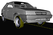 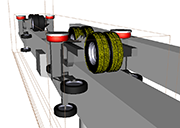 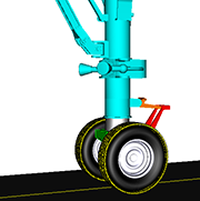 |
The UM FETire module contains tools for development and using finite element models of flexible tires. The flexible tire can be used in simulation of dynamics of road vehicles, monorail trains, and airplane landing gear.
The development of a flexible tire model requires the user to have a detailed description of the parameters of the tire's multilayer material.
The current version of UM offers the use of a flexible tire in the following main areas:
- Calculation of the curves of the massless tire model used in standard simulation of the dynamics of a wheeled vehicle (tabular model and TMEasy);
- Use for modeling vehicle dynamics in non-standard situations: hitting a curb, hitting a stone, driving through a damaged part of the road, etc.;
- Modeling of tire wear.
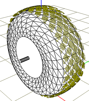 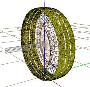 |
In the UM, a flexible tire is modeled by a shell using a trapezoidal finite element. The mathematical model of the element was developed by the authors of the module and is described in in the public domain papers and can be obtained via links paper1, paper2. The finite element model takes into account the multi-layer nature of the tire material.
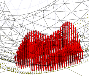 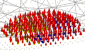 |
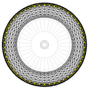
A brush model is implemented for contact interaction of the tire with the road surface. The contact surface of the tire is represented by a set of elastic massless bristles. One end of a bristle is connected to the FE and the other one can come into the contact with the supporting surface realizing elastic-dissipative interaction in the radial direction and friction in the tangent one.
The yellow dots correspond to the ends of the bristles making contact. As it is seen from the pictures, the bristles allow taking into account the tire tread pattern.
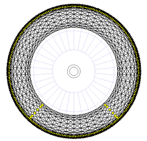  |
Reduced models have been implemented in order to speed up the simulation process. It the models either the upper part or the sides are replaced by superelements. Approximately two to three times the speedup is achieved.
Parallelization of calculations on multi-core computers allows to speed up the modeling approximately twice.
The virtual tire test rig and is used
- to create a tire by specifying geometric data, parameters of the multilayer material, description of the tread,
- to study some properties of the model (natural frequencies, damping level, deflection in the vertical, longitudinal and transverse directions depending on the corresponding load, etc.),
- to calculate the curves of the massless tire model used in standard modeling of the dynamics of a wheeled vehicle (tabular model and TMEasy),
- to create the reduced tire models;
- to create a finite element tire model which can be included in the model of a wheeled vehicle (car, monorail, motorcycle, etc.).
Test rig mode: automatic investigation of tire properties depending on load. Five static and three dynamic tests are performed for each load.
- Calculation of equilibrium under a given load
- Calculation of longitudinal static stiffness of the tire
- Calculation of lateral static stiffness of the tire
- Calculation of vertical static stiffness of the tire
- Calculation of static stiffness of the tire when turning around the vertical axis
- Freely rolling tire
- Calculation of the dependence of the lateral force and aligning moment on the lateral slip angle
- Calculation of the dependence of longitudinal force on slip
   |
| Example of calculation results: longitudinal, lateral forces and aligning moment depending on the corresponding slip at different wheel loads |
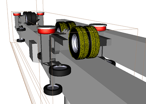 |
| Example of a monorail vehicle with four elastic tires |
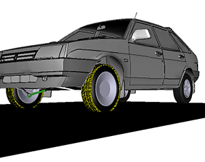 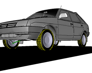 |
The FE tires can be activated and deactivated: in the picture on the left there are two active FE tires, in the picture on the right there are four.
Dynamic tire activation control is also implemented, where the tire is activated before an obstacle and deactivated after passing it.
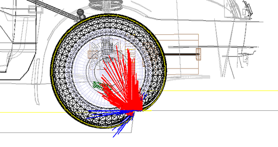 |
| Example: Drive over curb |
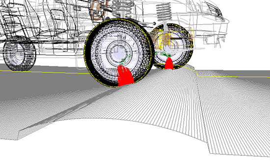 |
| Example: drive over speed bump |
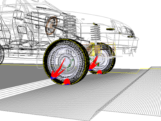 |
| Example: Drive over road damage |
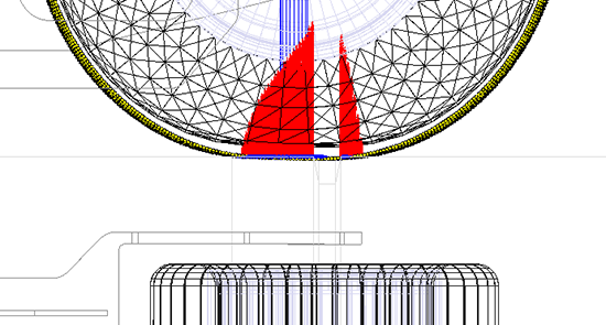 |
| Example: Drive a monorail traction wheel over a gap in the track structure |
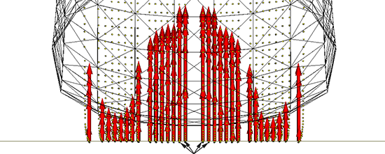 |
| Ribbons for wear computation |
The Archard model of tire tread wear is used, according to which the wear rate is proportional to the power of sliding friction forces. The contact surface of the tread is divided into ribbons. For an undeformed tire, each ribbon is a narrow cylinder with a diameter equal to the diameter of the wheel, and the cylinder axis is the axis of rotation of the wheel. The contact points of the tread with the road lie on the median circle of an individual ribbon
Wear within one ribbon is averaged, i.e. it is considered the same across the circumference and width of the ribbon. The computed wear variables are:
- The distributed wear rate factor
- The distributed accumulated wear factor
- Tire specific wear mm/1000km
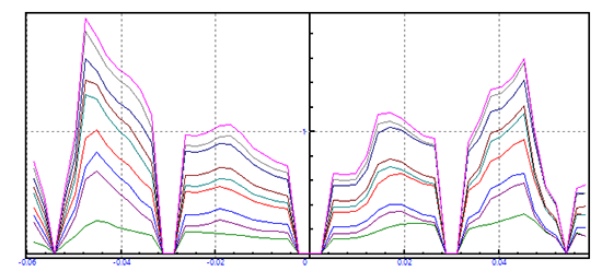 |
| Example of wear accumulation with increasing mileage |

